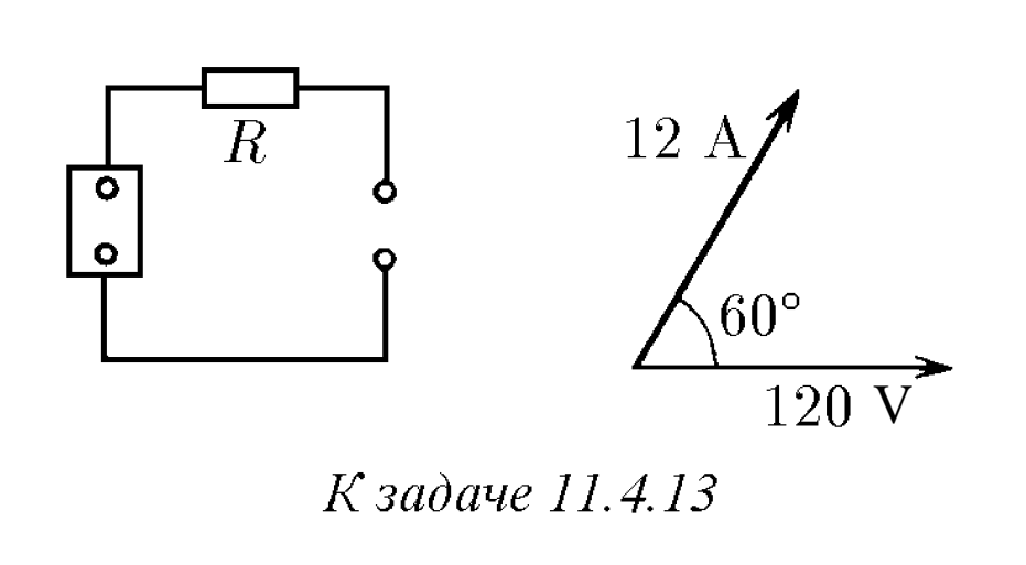
11.4.13. The values of voltage, current, and phase shift between voltage and current in the load circuit are shown in a vector diagram. Determine the source EMF amplitude if $R=10$ ohms.
Solution
For problem $11.4.13$
Let the current through the load (and the resistor $R$) be $I=(12\mbox{ A})\cdot e^{i\omega t}$, where $\omega$ is the angular frequency of the source. Then, the voltage drops across the load and the resistor are $V_L=(120\mbox{ V})\cdot e^{i(\omega t-\pi/3)}$ and
$$V_R=IR=(120\mbox{ V})\cdot e^{i\omega t},$$
respectively. Consequently, the EMF of the source is $\mathcal{E}=V_L+V_R$, which becomes