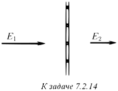
7.2.14∗. Prove that uniformly charged grid filaments with square cells focus a parallel electron beam that has passed through the cell to a point if the thickness of the filaments is much smaller than the cell size and the beam falls perpendicular to the grid plane. What is the focal length of such a cell if the electric field away from the grid plane is uniform and on the right is $E_1$, on the left is $E_2$, and the electron energy is $eV$ ?
Solution
In August 1931 C. J. Davisson and C. J. Calbick of Bell Labs reported that a hole in a charged plate between two uniform fields gathers electrons like a lens [1]. A year later they corrected the factor, and for a round hole $f = 4V/(E_2 - E_1)$[2]. This is formula (12) below, while their earlier $2V$ holds for a slit (14). Davisson had by then discovered electron diffraction, for which he shared the 1937 Nobel Prize.
In the same months M. Knoll and E. Ruska at the high-voltage laboratory of the Technische Hochschule Berlin were building geometrical electron optics [3,4]. In a note added in proof they cite the Davisson and Calbick abstract [3, p. 625], and in the second part Ruska describes exactly the effect of this problem, writing about mesh electrodes [4, p. 654]
Es werden daher Strahlen, die in großer Nähe der Drähte durch die Netzelektroden hindurchgehen, stärker abgelenkt, als Strahlen, die das Netz mehr in der Mitte einer Masche passieren.
that is, rays near the wires are deflected more than rays through the middle of a cell. This is (11). Their first microscope focused the beam with magnetic coils, after an idea of H. Busch, not with the electrostatic field of charged wires as here. For electron optics and the electron microscope Ruska received the 1986 Nobel Prize in Physics, 55 years after this work [5].
A real mesh is more complicated than charged wires. Read and co-workers computed meshes of round wires and of strips and found that the effective potential of the mesh plane differs from the potential of the wires themselves, which changes the field far away on both sides [6,7]. The potential of a grating of parallel line charges, one of the two families of wires in (5), (6), is written out in their appendix [6], and Williams, Read and Bowring treat the defocusing of a beam by the cells [8]. Today the lens (12) sits in every cell of the mesh in the wide-angle electrostatic lenses of photoelectron spectrometers [9]. A mesh in the beam corrects spherical aberration, as O. Scherzer proposed [10], and an ellipsoidal mesh accepts electrons up to $\pm 60^\circ$. The price is the blur that every cell adds, with different focal lengths in the tangential and sagittal planes at oblique incidence [9].
Here the electrons fly through vacuum independently, and the mesh imposes the period $d$ on them. In clean graphene the electrons collide with one another and flow like a viscous liquid, and the current can choose a period for itself. Above a critical drift velocity the uniform flow becomes unstable and breaks into running waves, an electronic analogue of Kapitsa's waves on a falling film, which radiate at the drift velocity divided by the wave period [11].
SI units. The $z$ axis is along the electrons' velocity (they fly from the field $E_1$ into the field $E_2$), the mesh lies in the plane $z=0$, the wires along $y$ are at $x = jd$ and the wires along $x$ at $y = id$. The cell is $0 \le x < d$,$0 \le y < d$.
$E_1$ and $E_2$ are positive when the field accelerates the electron (points against $\vec v$, as in the figure)
Keeping only the wires along $y$ (a slit), the whole jump (7) falls on them, $\lambda/(\varepsilon_0 d) = E_1 - E_2$, and the kick (11) doubles
$$f_0 = \frac{2V}{E_2 - E_1} \tag{14}$$
This is the first Davisson and Calbick formula [1]. In a square cell the jump is shared equally between the two families of wires, hence $4V$ in (12).
For the especially attentive, $v$ in (8) is constant while $eE_{1,2}d \ll eV$, i.e. $f \gg d$. Fig. 1 below shows the field (5), (6), drawn the same way as in [12], and Fig. 2 computes the trajectories in it without this approximation.
drag to rotate
Fig. 1. The field of the mesh. The mesh plane $z = 0$ and the space above and below every cell, the exact field (5), (6). The light lines are field lines of the whole field. They come in along $z$, uniform, and end on the wires, and the one on a cell's axis arrives at the cell's centre, where the lines on the plane start. The colour is the transverse field $|E_\perp|$, which is what turns the electrons towards the axis. It lives only near the mesh and falls by $e^{2\pi}$ within $d$ of it, so the figure is stretched threefold along $z$, and space is see-through where $|E_\perp|$ is weak.
0.00
0.40
formula $f/d =$20.0, computed 21.4with $E_2 \le E_1$ the cell spreads the beam
drag to rotate
Fig. 2. The beam through the mesh. A parallel beam crosses 9 cells, and the paths are computed in the exact field of Fig. 1. Every cell focuses its share of the beam to a point on its own axis, the foci lie in the plane $z = f$, and past it the beamlets open out and cross. The arrows $E_1$,$E_2$ show the direction of the far field. The foci are marked where each beamlet is narrowest, within $0.5d$ of the formula. Rays near the axis cross slightly further on and the outer ones slightly sooner, as in any lens.
Answer
$$f = \frac{4V(2E_2 - E_1)}{(E_2 - E_1)^2}$$
References
[1] C. J. Davisson and C. J. Calbick, Electron lenses (abstract, Minutes of the Pasadena Meeting), Phys. Rev. 38, 585 (1931), 10.1103/PhysRev.38.579.
[2] C. J. Davisson and C. J. Calbick, Electron lenses, Phys. Rev. 42, 580 (1932), 10.1103/PhysRev.42.580.
[3] M. Knoll and E. Ruska, Beitrag zur geometrischen Elektronenoptik. I, Ann. Phys. (Leipzig) 404, 607 (1932), 10.1002/andp.19324040506.
[4] M. Knoll and E. Ruska, Beitrag zur geometrischen Elektronenoptik. II, Ann. Phys. (Leipzig) 404, 641 (1932), 10.1002/andp.19324040602.
[6] F. H. Read, N. J. Bowring, P. D. Bullivant, and R. R. A. Ward, Penetration of electrostatic fields and potentials through meshes, grids, or gauzes, Rev. Sci. Instrum. 69, 2000 (1998), 10.1063/1.1148888.
[7] F. H. Read, N. J. Bowring, P. D. Bullivant, and R. R. A. Ward, Short- and long-range penetration of fields and potentials through meshes, grids or gauzes, Nucl. Instrum. Methods Phys. Res., Sect. A 427, 363 (1999), 10.1016/S0168-9002(98)01564-2.
[8] D. L. Williams, F. H. Read, and N. J. Bowring, Defocussing of charged particle beams transmitted through meshes, Nucl. Instrum. Methods Phys. Res., Sect. A 363, 120 (1995), 10.1016/0168-9002(95)00369-X.
[9] H. Matsuda, L. Tóth, F. Matsui, and H. Daimon, Evaluation of disturbing effect of mesh holes in wide-acceptance-angle electrostatic mesh lenses, J. Electron Spectrosc. Relat. Phenom. 195, 78 (2014), 10.1016/j.elspec.2014.05.013.
[10] O. Scherzer, Sphärische und chromatische Korrektur von Elektronen-Linsen, Optik (Stuttgart) 2, 114 (1947), scholar.google.com.
[11] P. Liong, A. Melnichenka, A. Bukhtatyi, A. Bilous, and L. Levitov, Spontaneous running waves and self-oscillatory transport in Dirac fluids, arXiv 2512.16571.
Discussion
Log in to join the discussion